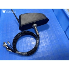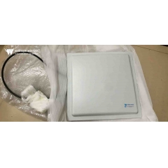

 Antenne routeur WiFi
Polarisation d'antenne : ce qu'elle est et pourquoi elle est importante
Temps de lecture estimé : 15 minutes
Chaque ingénieur en électronique sait que les antennes transmettent et reçoivent des signaux sous forme d'ondes électromagnétiques (ondes d'énergie électromagnétique), dont les propriétés peuvent être décrites par les équations de Maxwell. Comme de nombreux sujets techniques spécialisés, nous pouvons interpréter ces équations, ainsi que les règles de propagation et les caractéristiques des ondes électromagnétiques, selon plusieurs perspectives — allant de descriptions qualitatives relativement simples à des formules mathématiques complexes et détaillées.
La polarisation est l'une des nombreuses caractéristiques de la propagation de l'énergie électromagnétique. Ses effets et le degré auquel elle doit être prise en compte varient considérablement selon les différents scénarios d'application et les conceptions d'antennes correspondantes. Les principes fondamentaux de la polarisation s'appliquent à tous les rayonnements électromagnétiques, y compris les signaux radiofréquence (RF)/sans fil et l'énergie lumineuse, et la polarisation est largement utilisée dans le domaine de l'optique. Cet article couvre uniquement la bande de fréquences RF.
Qu'est-ce que la polarisation d'antenne ?
Pour comprendre la polarisation, il faut d'abord maîtriser les bases des ondes électromagnétiques. Une onde électromagnétique se compose d'un champ électrique (champ E) et d'un champ magnétique (champ H) se déplaçant dans la même direction. Le champ électrique et le champ magnétique sont perpendiculaires l'un à l'autre, et tous deux sont perpendiculaires à la direction de propagation de l'onde plane.
La polarisation est définie comme le plan de vibration du champ électrique lorsqu'on l'observe depuis l'extrémité émettrice dans la direction de déplacement de l'onde. En polarisation horizontale, le champ électrique oscille d'un côté à l'autre dans le plan horizontal ; en polarisation verticale, le champ électrique vibre de haut en bas dans le plan vertical (voir Figure 1).

Figure 1 : Onde électromagnétique avec des composantes de champ électrique et magnétique mutuellement perpendiculaires
Les antennes d'émission et de réception forment une paire d'antenneset les performances du système émetteur-récepteur atteignent leur maximum lorsque les deux partagent des plans de polarisation identiques. En référence à la célèbre réplique du film de 1979 Alien — « Dans l'espace, personne ne peut vous entendre crier » — il n'existe aucune distinction inhérente entre la polarisation horizontale et verticale dans l'espace extra-atmosphérique. Malgré cela, les théories de l'adaptation de polarisation et de l'alignement des antennes restent valables pour maximiser la transmission et la réception de l'énergie du signal.
Polarisation linéaire et circulaire
Les ondes électromagnétiques présentent plusieurs modes de polarisation :
- La polarisation linéaire de base comprend deux formes de polarisation mutuellement orthogonales (perpendiculaires) (voir Figure 2). Théoriquement, une antenne de réception à polarisation horizontale ne peut capter aucun signal émis par une antenne d'émission à polarisation verticale fonctionnant à la même fréquence, et inversement. Plus les orientations de polarisation des deux antennes sont proches, plus le signal reçu est fort ; l'efficacité du transfert d'énergie du signal atteint son maximum lorsque la polarisation est parfaitement adaptée.

Figure 2 : La polarisation linéaire offre deux formes de polarisation mutuellement orthogonales
- La polarisation inclinée est une variante de la polarisation linéaire. Comme les polarisations horizontale et verticale standard, cette définition ne s'applique qu'aux scénarios au sol. La polarisation inclinée forme un angle de ±45° par rapport au plan horizontal. Bien que la polarisation inclinée soit fondamentalement linéaire, lorsque les professionnels du secteur font référence à la « polarisation linéaire », ils désignent généralement uniquement les antennes à polarisation horizontale ou verticale.
- Les signaux émis ou reçus par des antennes à polarisation inclinée peuvent être captés par des antennes purement polarisées horizontalement ou verticalement, bien qu'avec une certaine perte de signal. Les antennes à polarisation inclinée sont idéales pour les cas d'utilisation où l'état de polarisation d'une ou des deux antennes est inconnu, ou lorsque la polarisation change pendant le fonctionnement.
- La polarisation circulaire (CP) est plus complexe que la polarisation linéaire. Dans ce mode de polarisation, le vecteur du champ électrique tourne continuellement pendant la propagation du signal. Lorsqu'on l'observe depuis l'extrémité émettrice vers l'extérieur, la rotation horaire du vecteur du champ électrique est appelée polarisation circulaire droite (RHCP) ; la rotation antihoraire est appelée polarisation circulaire gauche (LHCP) (voir Figure 3).

Figure 3 : Le vecteur du champ électrique des ondes électromagnétiques à polarisation circulaire tourne, se divisant en types droit et gauche
Les signaux à polarisation circulaire sont formés par la superposition de deux ondes électromagnétiques orthogonales présentant un décalage de phase de 90°. Trois critères doivent être satisfaits pour générer une polarisation circulaire : le champ électrique doit contenir deux composantes orthogonales ; les deux composantes doivent présenter une différence de phase de 90° ; et les deux composantes doivent avoir une amplitude égale. Les antennes hélicoïdales offrent une solution simple pour générer des ondes à polarisation circulaire.
- La polarisation elliptique (EP) est un dérivé de la polarisation circulaire. Comme les ondes à polarisation circulaire, les ondes à polarisation elliptique sont synthétisées à partir de deux ondes à polarisation linéaire. La polarisation elliptique se forme lorsque deux ondes à polarisation linéaire mutuellement perpendiculaires d'amplitudes inégales sont superposées.
Le degré de désadaptation de polarisation entre deux antennes est quantifié par le facteur de perte de polarisation (PLF), mesuré en décibels (dB). Sa valeur est déterminée par l'angle de polarisation entre les antennes d'émission et de réception. Théoriquement, le PLF est égal à 0 dB en cas d'adaptation parfaite de polarisation (aucune perte) ; si les deux antennes sont totalement polarisées orthogonalement, le PLF tend vers l'infini (atténuation complète du signal).
Dans les applications réelles, cependant, les antennes ne peuvent pas atteindre une polarisation parfaitement adaptée ou totalement orthogonale. Un mauvais alignement lors de l'installation mécanique, des erreurs humaines, la distorsion du canal, les réflexions par trajets multiples et d'autres facteurs introduisent tous une déviation angulaire de la direction de polarisation du champ électrique transmis. Même si deux antennes sont conçues pour une polarisation orthogonale, une fuite de polarisation croisée de 10 à 30 dB ou plus se produit encore en pratique. Dans certains scénarios, ce signal de fuite est suffisamment fort pour perturber la démodulation du signal souhaité.
Inversement, même avec une polarisation idéale et un alignement précis de deux antennes, les facteurs environnementaux réels peuvent pousser le PLF à 10 dB, 20 dB ou plus, dégradant ainsi la réception du signal. En termes simples, la polarisation croisée involontaire et les facteurs élevés de perte de polarisation produisent deux effets indésirables : ils introduisent des signaux interférents et atténuent la puissance du signal utile cible.
Pourquoi les caractéristiques de polarisation sont importantes
La polarisation suit une règle bidirectionnelle : plus les types de polarisation de deux antennes sont alignés et cohérents, plus la puissance du signal reçu est élevée. À l'inverse, une mauvaise adaptation de polarisation rend difficile la capture de signaux utilisables suffisants par les récepteurs cibles comme par les récepteurs d'interférence. Dans la plupart des scénarios, le canal sans fil modifie l'état de polarisation du signal transmis, ou l'un des deux émetteurs-récepteurs, voire les deux, ne peuvent pas maintenir une orientation d'antenne fixe et stationnaire.
Le choix du mode de polarisation est généralement déterminé par l'environnement d'installation et les conditions de propagation atmosphérique. Par exemple, les antennes à polarisation horizontale offrent de meilleures performances de signal et une polarisation plus stable lorsqu'elles sont montées près des plafonds ; en revanche, les antennes à polarisation verticale installées contre des murs latéraux présentent un comportement de polarisation plus proche de leurs spécifications nominales.
Les antennes dipôles courantes (dipôles standard / dipôles repliés) fonctionnent en polarisation horizontale dans un montage conventionnel (voir Figure 4). Si nécessaire pour correspondre à un mode de polarisation spécifique, l'antenne peut être tournée de 90° pour passer en polarisation verticale (voir Figure 5).
SHAPE \* MERGEFORMAT
Figure 4 : Les antennes dipôles sont généralement montées horizontalement sur des mâts pour une polarisation horizontale
SHAPE \* MERGEFORMAT
Figure 5 : Les antennes dipôles peuvent être installées verticalement sur des mâts pour une polarisation verticale lorsque l'application l'exige
La polarisation verticale est largement utilisée dans les talkies-walkies portatifs, tels que les appareils transportés par le personnel des services de secours d'urgence. Cela s'explique par le fait que la plupart des antennes radio à polarisation verticale présentent des diagrammes de rayonnement omnidirectionnels, ce qui signifie que les utilisateurs n'ont pas besoin de réajuster l'azimut de l'antenne même lorsque l'orientation de l'appareil portatif change constamment.
La plupart des antennesfonctionnant dans la bande des hautes fréquences (HF) de 3 à 30 MHz adoptent des structures d'antennes filaires longues simples tendues horizontalement entre des supports. Leur grande taille physique est dictée par la longueur d'onde correspondante (10 à 100 mètres), et ces antennes sont intrinsèquement à polarisation horizontale.
Curieusement, la bande a été nommée « haute fréquence » il y a plusieurs décennies, lorsque 30 MHz était considéré comme une gamme de hautes fréquences. Bien que cette appellation semble aujourd'hui dépassée, elle reste la désignation officielle de bande définie par l'Union internationale des télécommunications (UIT) et est toujours utilisée universellement.
La bande des ondes moyennes (OM) s'étend de 300 kHz à 3 MHz. La polarisation choisie par les stations de radiodiffusion dans cette bande dépend du fait que la station utilise des ondes de sol pour une couverture à courte portée avec un signal puissant ou des ondes ionosphériques pour des transmissions à longue distance. Globalement, les antennes à polarisation verticale offrent une propagation supérieure des ondes de sol, tandis que les antennes à polarisation horizontale sont mieux adaptées aux communications par ondes ionosphériques.
Les communications par satellite reposent fortement sur la polarisation circulaire. Les satellites modifient constamment leur attitude par rapport aux stations au sol et aux autres satellites. L'efficacité de transmission du signal atteint son maximum lorsque les deux extrémités d'émission et de réception utilisent des antennes à polarisation circulaire ; l'association d'antennes à polarisation linéaire avec des antennes à polarisation circulaire fonctionne, mais introduit un facteur de perte de polarisation mesurable.
Les caractéristiques de polarisation sont tout aussi essentielles pour les systèmes 5G. Certains réseaux d'antennes MIMO (Multiple-Input Multiple-Output) 5G exploitent la technologie de polarisation afin d'utiliser plus efficacement les ressources spectrales, augmentant ainsi les débits. Cela est obtenu en combinant différents modes de polarisation des signaux avec le multiplexage spatial des antennes (diversité spatiale). Ces systèmes transmettent simultanément deux flux de données indépendants, chaque flux étant envoyé vers des antennes distinctes ayant des polarisations mutuellement orthogonales, ce qui permet au récepteur de démoduler séparément les deux flux. Bien que des facteurs non idéaux, notamment les trajets de propagation, la distorsion du canal, les réflexions et les effets de trajets multiples, introduisent une légère interférence de polarisation croisée, les récepteurs l'atténuent en interne.
Conclusion
La polarisation est une caractéristique essentielle mais souvent négligée des antennes. La polarisation linéaire (y compris les variantes horizontale et verticale), la polarisation inclinée, la polarisation circulaire et la polarisation elliptique conviennent chacune à des scénarios d'application distincts. L'orientation relative et le degré d'adaptation des antennes aux extrémités d'émission et de réception déterminent directement les performances globales de l'ensemble de la liaison RF. Une grande variété d'antennes standard couvrant tous les types de polarisation et toutes les bandes de fréquences RF sont disponibles dans le commerce afin de fournir des schémas de polarisation adaptés à toutes les applications cibles.